Mo-Al2O3太阳能选择吸收涂层的制备及其光学性能
张文辉,张敏,李影,殷雪,李美仪,李小晶
摘要:选用金属Mo作为红外反射层,Mo-Al2O3作为吸收层,Al2O3作为减反射层,利用磁控溅射镀膜技术,在抛光的316L不锈钢片上制备具有双吸收层的Mo/Mo-Al2O3/Al2O3太阳能选择吸收膜系,研究减反射层和高、低金属吸收层的厚度及其金属体积分数对膜系选择吸收性能的影响。结果表明,当减反层厚度为50nm时,所得膜系的选择吸收性能最佳。高金属吸收层厚度的增加会使薄膜反射率的骤升阈值发生红移,薄膜的发射率升高,但其厚度过高,则会影响薄膜的干涉效应。低金属吸收层厚度的增加会导致可见光波段的吸收率增加,红外波段的发射率上升,薄膜反射率的骤升阈值红移。高金属吸收层中金属体积分数增加会导致它的方块电阻降低,使薄膜的红外发射率下降。低金属吸收层中金属体积分数的增加,会导致薄膜的红外干涉下降,使其发射率升高,获得薄膜的最佳吸收率为0.922,发射率为0.029。

0 Introduction
Solar selective absorption coating is a key material for solar thermal utilization and has an extremely important impact on improving the photothermal conversion efficiency [1]. The coating maximizes the conversion of sunlight into heat by maintaining high absorption of the solar spectrum and high reflection of far-infrared light. According to different absorption principles, selective absorption coating can be divided into semiconductor coating, optical interference coating, cerceral coating and surface texture coating [2].
At present, the preparation methods of selective absorption coatings mainly include coating method, sol-gel method, electrochemical deposition method, chemical vapor deposition method and physical vapor deposition method. In 1996, Wu Shaoqing et al. [3] used silica sol and iron powder to configure solar heat absorbing coating, whose absorption rate was 0.94 and emissivity was 0.41. Due to high emissivity, the service life was short. The sol-gel method needs to introduce complex chemical processes in the preparation process of solar selective absorption coating, and the components are complex. At present, the research mainly focuses on the material system based on MnCuO[4] and cobalt oxide [5-6]. Electrochemical deposition process is simple, low cost and has good optical properties, but the waste liquid may cause pollution to the environment. Among them, Ding Dawei et al. [7] deposited Cu in anodized Al2O3 micropores by AC deposition method to prepare a coating with good optically selective performance. Although vacuum evaporation coating is simple and convenient, easy to operate, and high efficiency, the film preparation process repeatability and film-base binding force are poor. Zhou Bang Wei et al. [8] deposited a double-layer black chromium selective absorption coating with absorptivity of 0.89~0.91 and emissivity of 0.05~0.07 by using this method. Magnetron sputtering method uses energy-carrying ions to bombard the surface of the target material, and the sputtered atoms or molecules are deposited on the substrate to form a thin film, which is an important preparation method for selective absorption coatings in the future [9]. In 2000, Xie Guangming [10] successfully prepared MoAlN solar selective absorption coating by planar three-target magnetron sputtering method. The absorptivity is greater than 0.9 and the emissivity is less than 0.1. In 2005, Wang Bao-wei et al. [11] prepared an excellent NiCr series dark blue solar spectral selective absorption film by DC reactive magnetron sputtering method, and tested its absorption rate of 0.90~0.94 and emissivity of 0.08~0.16. In 2008, Hao Lei et al. [12] prepared TiAl/TiAlN/TiAlON/TiAlO coating by using multi-arc ion plating and controlling the flow rate of O2 and N2. The results showed that the grain size distribution of the coating was uniform, and the absorptivity of the coating was higher than 0.90 in the vision-near infrared region. In the infrared region, the emissivity of the film is 0.09~0.19, and the developed coating has good spectral selective absorption. In 2013, Yang Zhongzhou [13] prepared Ti-DLC solar selective absorption coating by using intermediate frequency magnetron sputtering, and optimized the Al metal reflection layer with Matlab. The absorption rate and emissivity of the coating prepared were 0.901 and 0.075. In 2015, Zhang Min’s research group [14] selected W-Aln metal-dielectric solar spectral selective absorption coating for research, used Mathematica software to optimize the combination of W volume fraction of metal, AlN thickness of absorption layer and AlN thickness of reflection layer, and obtained W/ W-Aln /AlN solar selective absorption coating. The absorptivity reaches 0.920 and the emissivity reaches 0.022.
To sum up, there are still some problems in solar selective absorption coatings, such as low absorption efficiency, complex film preparation process, poor repeatability, and inability to work at medium and high temperature. Moreover, the above literature rarely studies in detail the influence of the thickness of the absorption layer and the change of metal volume fraction on the selective absorption performance of the film. However, in the preparation of the whole film system, Changing the filling factor of the absorption layer and the thickness of the film, and studying the variation rule of the reflection spectrum of the film system can provide important test basis and data support for solving the above problems. Therefore, in this paper, DC-RF double target magnetron sputtering coating technology is used to prepare a single layer of Mo-Al2O3 metal medium type film on the mechanically polished 316L stainless steel sheet. The relationship between Mo target current and metal Mo content in thin film was studied. On this basis, Mo/ Mo-al2o3 /Al2O3 solar selective absorption multilayer films with double absorption layers were prepared. The thickness of the films and the volume fraction of metal in the films were controlled by controlling sputtering time and Mo target current. The influence of the thickness of antireflective layer, high and low metal absorbing layer and the volume fraction of metal in high and low metal absorbing layer on the selective absorption performance of film system was studied.
1. Membrane system design, preparation and characterization methods
Metal-medium selective absorption coating, also known as Cermet coating, is formed by small metal particles dispersed in the dielectric. The metal band transition and the resonance of small particles make it have a strong absorption effect on the solar spectrum and transparent to the infrared spectrum. The volume fraction of metal particles and the optical thickness of the film play an important role in the optical properties of the film. In order to ensure the high absorptivity of the film layer, the absorption layer should have appropriate thickness and metal particle volume fraction. However, if the film is too thick or the volume fraction is too high, the absorption peak will move to the direction of long wave, resulting in the increase of emissivity. Because the absorption peak is not steep enough, the emissivity will rise sharply when the temperature rises. In order to overcome the above phenomenon, ZhangQC from the University of Sydney has proposed an interference-plus absorption dual-absorption layer structure. From the inside out, High metal volume fraction cermet, HMVF cermet) and Low metal volume fraction cermet (LMVF cermet) have obtained satisfactory selective absorption effects under the condition that the membrane layer is not too thick or the volume fraction is low, and the results are obtained from the interference effect and thin film analysis. The preparation and optical properties of Mo-Al2O3 solar selective absorption coating 97 The energy absorption angles all indicate that the four-layer structure with double absorption layers is the best membrane structure [15-16]. This double absorption layer structure is also used in the paper. The structure of the film system is shown in Figure 1, which successively consists of 316L stainless steel, Mo infrared reflection layer, HMVF cermet with high Mo volume fraction, LMVF cermet with low Mo volume fraction and Al2O3 antireflection layer from bottom to top. The band gap of the film can be adjusted by changing the metal volume fraction. The band gap decreases with the increase of the metal volume fraction. The Mo volume fraction increases gradually from the outside to the inside, the band gap of each sublayer decreases gradually, the solar spectral transmittance decreases gradually, but the absorption of solar energy increases gradually, finally achieving the effect of layer by layer absorption.
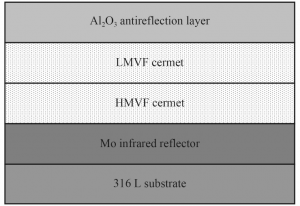
FIG. 1 Structure diagram of metal-medium type selective absorption coating
Mo and Al2O3 with purity of 99.99% were selected as the target material, the size of the target material was 54mm×4mm, the Mo target and Al2O3 target were respectively through DC and RF power supply, the sample platform was located 100mm above the sputtering target. 316L stainless steel sheet with the size of 20mm×20mm×2mm was selected as the substrate, which was immersed in acetone, anhydrous ethanol solution and deionized water successively, cleaned by ultrasonic for 15min, and finally dried with nitrogen before being placed into vacuum chamber. The backbottom vacuum was pumped to 5×10⁻³Pa, and argon gas was applied to maintain the vacuum at 2.0Pa. After negative bias was applied to the substrate, glow cleaning was performed for 10min to clean the surface and improve the surface activity. Then the vacuum degree was adjusted to 0.5Pa, and the Mo target and Al2O3 target were opened successively to prepare the Mo/ Mo-al2o3 /Al2O3 selective absorption coating. Proper adjustment of deposition time and sputtering current is adopted to ensure the required thickness of each sublayer.
The surface morphology of the film was observed by SU8000 type field emission scanning electron microscope, and the EDX attached to the film was used for energy spectrum analysis to determine the element composition and the relative content of each element in the film. The film thickness was measured by Z-Type 700 step meter. The Lamda750s ultraviolet-visible spectrophotometer was used to measure the reflectance of the coating at different wavelengths. The selective absorption properties of the coating are measured by the absorptivity α[17] and the emissivity ε[18], which can be calculated by equations (1) and (2), respectively.
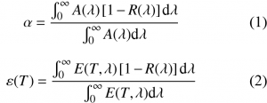
Where, R(λ) is monochromatic spectral reflectance; A(λ) is the solar radiation spectrum under AM1.5 atmospheric environment. R(λ,T) is spectral reflectance; E(T,λ) is the monochromatic radiation intensity of the black body at temperature T:

C1=3.74×10⁻¹⁶W·m2; C2=1.44 x 10⁻²m·K.
2 Results and discussion
2.1 Relationship between metal Mo content and sputtering current in thin films
The sputtering power of the Al2O3 target was fixed at 200W, the deposition time was 40min, the working pressure was 1.5Pa, and the sputtering current of the Mo target was set at 0.03, 0.05, 0.07 and 0.09A, respectively. Four groups of Mo-al2o3 films containing different Mo volume fractions were prepared. Through component analysis of the resulting Mo-al2o3 composite thin film, the relationship curve between metal Mo sputtering current and metal Mo volume fraction was obtained, as shown in Figure 2.
It can be seen from Figure 2 that the volume fraction of metal Mo in the film increases with the increase of sputtering current of the Mo target. The least square method was used for linear fitting of the data, and the relationship between metal Mo volume fraction (y) and Mo target current (x) was obtained, as shown in Equation (4).
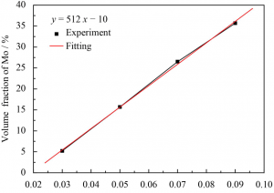
Fig.2 Relationship between Mo content in the absorbed layer and sputtering current
According to this, the volume fraction of metal Mo in the absorption layer can be calculated under a certain sputtering current.
2.2 Surface morphology of the film system
Figure 3 shows the surface morphology of the Mo/ Mo-al2o3 /Al2O3 selective absorption multilayer film. As can be seen from Figure 3, the surface of the film is flat and compact, without obvious defects such as large particles.
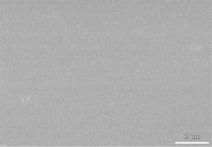
Fig.3 Surface morphology of Mo/Mo-Al2O3/Al2O3 selective absorbing coating
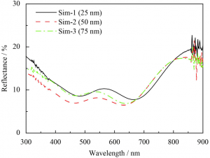
Fig.4 Reflectance curves of Mo/Mo-Al2O3/Al2O3 selective absorbing coatings with different thickness of antireflective layer for 25, 50 and 75nm
2.3 Effect of reducing the reflection layer thickness on the optical properties of the film system Mo/ Mo-al2o3 /Al2O3 selective absorption multilayers were prepared on the polished surface of 316L stainless steel. In the process of coating, the Mo target was opened to deposit a metal infrared reflection layer with a thickness of 90nm on the substrate, and then the Al2O3 target was opened to deposit high and low metal absorption layers with Mo volume fraction of about 50% and 25%, and the Al2O3 anti-reflection layer was deposited. The film preparation parameters are shown in Table 1, and the reflection spectrum of the film system obtained by testing is shown in Figure 4. When the thickness of the anti-reflection layer increases from 25 nm to 50nm, the reflectance of the film system to the wavelength range of 300~700nm decreases, that is, the absorption performance improves, and the absorption peak shifts blue. The position of the absorption peak did not change significantly when the thickness of the antireflection layer was increased to 75nm, but the reflectance of the film system at the short wave increased, and the absorption performance of the film system became worse.
According to the interference principle of multilayer thin film [19], when the incident light and reflected light are superimposed, there will be destructive interference, thus improving the absorption performance. However, with the increase of the thickness of the anti-reflection layer, the interference point will move to the shortwave direction, so the phenomenon of blue shift occurs at the absorption peak. Since the energy of sunlight is mainly concentrated in the 300-700nm wavelength region, the lower the reflectance R in this region, the higher the absorptivity α of coating (α+τ+R=1, τ=0, where α is the absorptivity, τ is the transmittance, R is the reflectance). Therefore, combined with Figure 4, the film system obtained when the thickness of the anti-reflection layer is 50nm has the best selective absorption performance.
Table1 Process parameters with changing the thickness of the antireflective layer

2.4 Influence of thickness of high metal absorbing layer on optical properties of film system
In the process of film preparation, the infrared reflector with thickness of 90nmMo was first prepared, and then the Mo target and Al2O3 target were simultaneously opened to prepare high and low metal absorption layers with volume fraction of metal particles of 25% and 10%, respectively. Finally, the sputtering current of the Mo target was turned off and the Al2O3 antireflection layer with a thickness of 50nm was deposited. The specific parameters are shown in Table 2, and the reflectance map of the tested sample is shown in Figure 5.
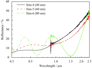
Fig.5 Reflectance curves of Mo/Mo-Al2O3/Al2O3 selective absorbing coatings with different thickness of HMVFfor40, 60 and 80nm
Table 2 Process parameters with changing the thickness of high metal absorption layer

As can be seen from FIG. 5, when the thickness of the highly absorptive layer increases from 40nm to 60nm, the selective absorption of the film to the visible part decreases, and the threshold of the reflectance of the film suddenly rises to redshift. However, the reflectance ratio in the infrared band decreases, that is, the emissivity increases. When the thickness of the high metal absorbing layer continued to increase to 80nm, it was found that the film appeared obvious interference effect, the reflection minimum was close to the reflection zero, and the absorption peak was obvious. The difference between the peak and the trough was large, and the reflectance threshold of the film continued to redshift at about 1500nm. Due to the relatively high metal content in the high-metal absorbing layer, the band-gap width is small. With the increase of its thickness, more long-wave light will be absorbed and short-wave light will be reflected [19], resulting in the increase of the reflection ratio at short-wave and the increase of the interference effect of the film, so that the reflectance threshold of the film will rise sharply to the long-wave.
2.5 Influence of low metal absorption layer thickness on optical properties of film system
Table 3 shows the specific technological parameters in the film preparation process. Among them, the volume fraction of metal particles in the high and low metal absorption layers remained unchanged at 25% and 10%, and only the thickness of the low Mo absorption layers changed. The reflection spectrum of the measured sample is shown in Figure 6.
Table 3 Process parameters with changing the thickness of low metal absorption layer

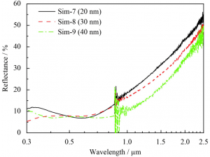
Fig.6 Reflectance curves of Mo/Mo-Al2O3/Al2O3 selective absorbing coatings with different thickness of LMVF for 20, 30 and 40nm
It is not difficult to see from Figure 6 that when the thickness of the absorption layer with low Mo volume fraction increases, the absorption performance of the film system to visible light does not change significantly, but its reflectance in the infrared band decreases, that is, its emissivity increases, and the threshold value of the reflectance of the film system surges red shift. This is because the low absorption layer is between the high absorption layer and the anti-reflection layer, its conductivity is lower than that of the high absorption layer, that is, the resistance of the block is higher than that of the high absorption layer, its dielectric properties are strong, mainly absorb short wavelength light, while the influence of light interference is obvious, when the thickness increases, the light path of the sun into the film becomes larger, according to the principle of thin film interference, The wavelength values of the corresponding cancelling and phasing interference points move towards the long wave direction, resulting in the sudden rise threshold of the reflectance curve moving towards the long wave direction. Therefore, the thickness of the high absorption layer, low absorption layer and anti-reflection layer should match each other to increase the absorption rate in the visible band and reduce the emissivity in the infrared band. This conclusion is consistent with the conclusion obtained by the previous research group using Mathematica software to optimize W-AlN coating structure [14].
2.6 Influence of metal volume fraction in high metal absorption layer on optical properties of film system
In the process of film preparation, the volume fraction of metal particles in the absorption layer was controlled by changing the Mo target current. Firstly, the 90nm Mo infrared reflection layer was deposited on the substrate, and then the Mo target and Al2O3 target were opened at the same time to deposit high and low metal absorption layers with the thickness of 50 and 35nm, respectively. Finally, an anti-reflection layer with the thickness of 50nm was sputtered on the outer layer. Parameters are shown in Table 4, and the measured reflectance spectrum is shown in Figure 7.
Table 4 The process parameters with changing the metal content of high metal absorption layer

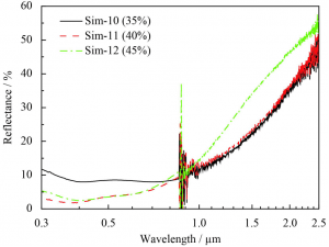
Fig.7 Reflectance curves of Mo/Mo-Al2O3/Al2O3 selective absorbing coatings with different Mo volume fraction of the high metal absorption layer for 35%, 40% and 45%
It is not difficult to see from Figure 7 that the volume fraction of metal Mo in the high-absorption layer increases from 35% to 40%, and the visible light absorption performance of the film system increases. However, when the volume fraction of metal Mo is increased to 45%, the reflection of the film system to the near infrared region is enhanced, and the emissivity decreases.
According to the Bruggeman aggregate microstructure theory [20], the band gap of the absorption layer gradually decreases with the increase of the volume fraction of metal particles in the absorption layer, and the light absorption capacity increases. This explains the increase of the metal Mo volume fraction from 35% to 40% in the high absorption layer and the enhancement of visible light absorption by the film system. On the other hand, the conductivity of the absorbing layer also increases relatively with the increase of the volume fraction of metal, and the metal properties of the film layer are enhanced, which leads to the increase of the reflection ratio at the long wave, and more light is reflected [21]. As a result, the reflection of the film system on the near infrared region is enhanced, and the emissivity is reduced.
2.7 Influence of the change of metal volume fraction in low metal absorption layer on the optical properties of thin films
The film preparation parameters are the same as above, with the thickness of high and low absorption layers being 50nm and 35nm respectively. The specific parameters are shown in Table 5, and the reflectance map is shown in Figure 8.
Table 5 Process parameters with changing the metal volume fraction of low metal absorption layer

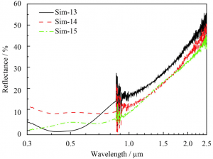
Fig.8 Reflectance curves of Mo/Mo-Al2O3/Al2O3 selective absorbing coatings with different Mo volume fraction of the low metal absorption layer for 15%, 20% and 25%
The band gap width of the low absorption layer is larger than that of the high metal absorption layer but smaller than that of the anti-reflective layer. The increase of the metal volume fraction will affect the interference effect of the film system. As can be seen from Figure 8, when the metal volume fraction of the low absorption layer increases from 15% to 20%, the absorption performance of the film to visible light becomes weaker, and the metal volume fraction of the low absorption layer continues to increase. Although the absorption performance of the film to visible light increased, it formed a wave peak at about 400~580nm, which happened to be in the wavelength range of high solar radiation, so that the absorption rate of solar energy decreased. The emittance of the film system increased with the increase of the volume fraction of metal particles in the low absorption layer. The main reason is that the increase of metal Mo content in the low metal absorption layer decreases the band gap width and increases the conductivity, making the absorption limit of the film move in the direction of long wave, affecting the interference of the film on long wave light, resulting in the increase of its emissivity.
3 Conclusion
(1) Single layer Mo-al2o3 metal-dielectric film was prepared on polished 316L stainless steel sheet by Dc-RF double-target magnetron sputtering coating method. On this basis, Mo/ Mo-al2o3 /Al2O3 solar selective absorption multilayer film system with double absorption layer was prepared. The content of metal Mo in Mo-al2o3 film increases with the increase of sputtering current, the sputtering current of Mo target increases by 0.01A, and the volume fraction of metal Mo in MoAl2O3 film increases by about 5%. The absorption limit and interference peak of the film system are mainly affected by the thickness of the anti-reflection layer. When the thickness of the anti-reflection layer is 50nm, the absorption performance of the film system is the best.
(2) With the increase of the thickness of the high metal absorbing layer, the threshold of the reflectance of the film will be redshifted, and the emissivity of the infrared band of the film will increase. However, if the thickness is too large, the interference effect will increase, resulting in more obvious peaks and troughs. The increase of the thickness of the low metal absorbing layer will lead to the increase of the absorption rate of the film in the visible region, the increase of the emissivity of the infrared band, and the red shift of the sudden rise threshold of the reflectance.
(3) The change of metal volume fraction in the high metal absorption layer will affect the emittance of the film in the infrared band. With the increase of metal volume fraction, the emittance of the film in the infrared band will decrease. The change of metal volume fraction in the low metal absorption layer will affect the selective absorption effect of the film. With the increase of metal volume fraction, it will affect the interference of long wave and increase the absorption of long wave, so that the infrared interference of the film decreases and the emissivity increases. Considering the influence of different processing parameters on the selective absorption of the film system, the optimum absorption rate and emissivity of the film are 0.922 and 0.029.