氧化铝包覆Li1+xMn0.54Co0.13Ni0.1+yO2电化学离子交换法制备钠离子电池正极材料
Layered cathode materials of the type Na1+xLi0.05Mn0.54Co0.13NiyO2-z (0 < x < 0.1, y ¼ 0.13 or 0.2, z < 0.1) were prepared by direct ion-exchange reactions, starting from Li1.2Mn0.54Co0.13Ni0.13O2 and Li1.13Mn0.54Co0.13Ni0.2O2. They were examined vs. Na foil or sodiated hard carbon anodes as high capacity positive electrode materials for Na ion batteries with an initial reversible capacity >200 mA h g-1 . Analysis by X-ray and electron diffraction reveals that the new materials are initially mixtures of rhombohedral and monoclinic phases. Attempts to prepare layered compounds with similar compositions by chemical means resulted in phases of hexagonal structure with rather poor electrochemical activity, emphasizing the importance of the synthesis by electrochemical ion exchange. Also, the stability of electrochemically prepared Na insertion cathode materials in cycling experiments was insufficient for practical consideration. In turn, cathodes prepared from the same Li precursors coated by a thin layer of alumina via atomic layer deposition, followed by electrochemical Na/Li ion exchange, demonstrated stable capacity (>170 mA h g-1 ) during prolonged cycling. Their average discharge voltage was 300 mV higher compared to the counterpart uncoated Na intercalation cathodes. The structure and behavior of these electrodes were thoroughly explored by a variety of analytical and surface tools, in conjunction with electrochemical techniques.
Introduction
Following the impressive success of Li-ion batteries (LIBs),1–4 non-aqueous sodium electrochemistry is now becoming part of the forefront of modern electrochemistry.5–8 The importance of Na-ion batteries (NIBs) is due to the high abundance of sodium in the Earth’s crust, ensuring an unlimited supply that promises low cost.9,10 Also, in contrast to lithium, sodium does not alloy with aluminum, and therefore, Al can be used as an anodic current collector instead of the more expensive Cu. Also, inexpensive polymeric binders can be used for preparation of composite electrodes (e.g., carboxymethyl cellulose instead of polyvinylidene fluoride), together with low-cost solvents (water instead of N-methyl-2-pyrrolidone, for example).11 However, the sodium ion is 0.3 -A larger than the lithium ion (crystallographic radii are 1.06 and 0.76 -A, respectively) and about three times heavier (6.9 and 23 g mol-1 , respectively). The crystallographic radius has a significant effect on interactions with frameworks of possible host materials and plays a major role in defining electrochemical characteristics. The specific gravimetric capacity is three times lower for the Na-metal compared to lithium (1165 vs. 3829 mA h g-1 , respectively). Lastly, the 0.3 V higher standard potential of the Na-metal vs. the Li-metal also contributes to the lower energy density of NIBs compared to LIB analogues.12–15
Extensive research has been conducted for Li- and Mn-rich layered metal oxide materials.16–19 These materials are structurally integrated two-component solid solutions, referred to by notations such as xLi2MnO3(1-x)LiMO2 (where M is a mixture of transition metals, usually Mn, Ni and Co), which are found in rhombohedral (LiMO2) and monoclinic (Li2MnO3) structures, where Li ions are located in octahedral sites.20–22 Activation of the Li2MnO3 component during the first charge process involving polarization to potentials >4.5 V vs. Li induces pronounced structural changes that result in relatively high reversible specific capacity. These materials can exhibit a specific capacity >250 mA h g-1 in the potential range of 4.6–2.5 V (after activation), with a mean discharge voltage of around 3.7 V vs. Li.23,24
It was expected that analogous Na insertion cathode materials with a composition of Na2MnO3–NaMO2 could be developed.25 Recent reports on Na insertion cathode materials present compositions analogous to the integrated Li- and Mnrich cathode materials.23–25 A number of recent studies attempted electrochemical synthesis of sodium cathode materials from Li-based materials. For example, the electrochemical ion-exchange method was applied to obtain NaFePO4 from LiFePO4, 26 and was also applied to Li-rich layered materials.27,28 The ion-exchange processes reported in the literature included three steps: first, lithium cells were fabricated and charged to 4.6 V vs. Li, resulting in de-insertion of lithium ions from electrodes and activation of the cathode material. Second, the lithium cells were disassembled, and the de-lithiated electrodes were rinsed with pure solvent in order to remove residual lithium originating from the Li salt in the electrolyte. Finally, sodium cells were assembled with de-lithiated, activated cathodes, Na salt solutions and Na anodes. Further sodiation and cycling were carried out with these cells.
The goal of the present work was preparation of analogous cathode materials with high Na insertion specific capacities. Two approaches were examined:
- Synthesizing Li- and Mn-rich cathode materials, such as Li1.2Mn0.54Co0.13Ni0.13O2 and Li1.13Mn0.54Co0.13Ni0.2O2, followed by their utilization as precursors for Li / Na ion exchange.
- Synthesizing Na insertion cathode materials with similar compositions, using methods such as self-combustion reactions, proved to be highly effective for preparation of Li insertion cathode materials.
In our synthesis by ion exchange, the initial Li- and Mn-rich cathodes were activated (de-lithiated) and cycled in Na cells that contained sufficiently large amounts of free Na ions. Thus, the electrochemical reactions in the cells were dominated by Na ion reactions. The main starting material Li1.13Mn0.54Ni0.2Co0.13O2 (Li-a) was directly converted to Na1+xLi0.05Mn0.54Co0.13Ni0.2O2-z (0 < x < 0.1, z < 0.1) by an electrochemical ion exchange procedure.
The secondary objective of this study was to reduce detrimental reactions between cathodes and electrolyte solutions by forming a protective layer that enables sodium ion diffusion/ migration.29 These materials were coated with aluminum oxide using the atomic layer deposition method (ALD). By applying the ion-exchange procedure to coated Li- and Mn-rich cathode material precursors, we expected to achieve high performance Na intercalation cathode materials. Rigorous electrochemical characterization, in conjunction with structural, microscopic and spectroscopic analyses was carried out, in order to understand the behavior of the new Na insertion cathode materials.
Experimental
Synthesis and structural characterization
Li1.13Mn0.54Ni0.13Co0.2O2 was obtained from BASF (Germany). The Li-and Mn-rich cathode Li1.2Mn0.54Ni0.13Co0.13O2 was synthesized by the freeze-drying method. Appropriate amounts of LiNO3, Mn(NO3)2, Ni(NO3)2 and Co(NO3)2 solutions were mixed by stirring with the aid of a magnetic bar. The solutions containing desirable element mixtures were then frozen at -28°C for about 24 hours and transferred into a freeze-drier operating at -80°C under vacuum for about 20 hours in order to dry them by water sublimation. The nitrate salt mixtures were transferred into nickel containers and heated in order to decompose them and obtain lithiated transition metal oxide mixtures. These were further heated at 500°C for three hours, ground and annealed at 900°C for about 15 h in air in order to obtain final cathode materials.
Materials characterization
The synthesized materials were subjected to an elemental analysis using the inductively coupled plasma–atomic emission spectrometry (ICP-AES) technique with an Ultima-2 spectrometer (Jobin Yvon Horiba). X-ray diffraction (XRD) studies were performed with a Bruker Inc. (Germany) AXS D8 Advance diffractometer (q–q reflection geometry, Cu Ka radiation source, receiving slit of 0.2 mm width, high-resolution energydispersive detector). High-resolution TEM (HRTEM) studies including electron diffraction and energy dispersive spectroscopy (EDS) were carried out using a JEOL-JEM 2100 electron microscope with a LaB6 emitter operating at 200 kV. The samples for TEM studies were prepared by dispersing and sonicating the powdered samples in ethanol and adding a few drops of the resulting suspension to a TEM copper grid.
Electrodes, electrochemical measurements and cell preparation
The composite cathodes were fabricated by mixing 80 wt% of the active mass, 10 wt% of carbon black, and 10 wt% of a polyvinylidene fluoride (PVDF) binder in NMP. A planetary centrifugal vacuum mixer was used to shake the vials at 2000 rpm for 5 min under vacuum. The obtained slurry was cast onto aluminum foils and coated with a doctor blade. The electrodes were then dried overnight under vacuum at room temperature. The resulting coated foils were cut into discs with a diameter of 14 mm, which were weighed and dried at 120°C overnight in a vacuum. The typical loading of the active mass was 3–4 mg cm-2 . The electrochemical performance was examined using 2325 coin-type cells (parts obtained by NRC Canada) assembled in an argon-filled glovebox (MBraun). Sodium metal foils were used as both counter and reference electrodes. The electrolyte solution was 1 M NaPF6 (Kishida) in polypropylene carbonate (PC, Woke) containing 2% fluoroethylene carbonate (FEC). Standard polyethylene separators (from Celgard) were used.
The electrochemical properties were measured with a Maccor computerized multichannel battery cycler, mostly in galvanostatic mode. The galvanostatic charge–discharge cycling experiments were carried out at current densities around 10– 50 mA g-1 over different potential ranges. Cyclic voltammetry (CV) and electrochemical impedance spectroscopy (EIS) were performed using a VMP Bio-Logic potentiostat with a 1287/1260 FRA system from Solartron.
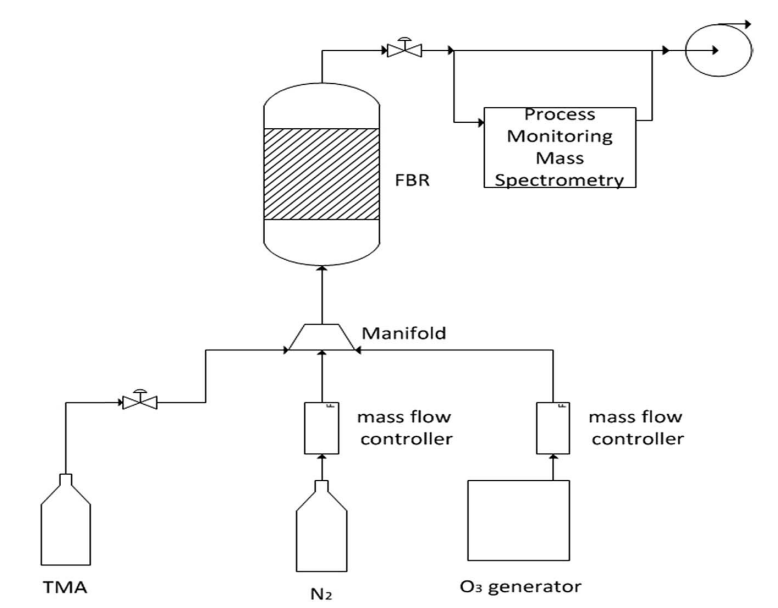
Fig. 1 A schematic presentation of the ALD machine and its operation.
Coating of the cathode materials was carried out via ALD processes performed in the system described schematically in Fig. 1. It includes a TFS-200-189 fluidized bed reactor (FBR, Beneq) with a diameter of 38 mm. Trimethyl-aluminum (TMA, Strem Chemicals Inc.) was pre-loaded in a 50 ml Swagelok container. Ozone was introduced into the system through a BMT 803N ozone generator (BMT, Messtechnik), and highly pure nitrogen gas was used as the carrier gas.
A batch of 20 g of a Li-based cathode powder was placed in the FBR on a two-layer porous (60–70%) 316 stainless steel membrane. The average pore sizes of the first and second layers were 40 and 20 mm, and their thickness was 2 mm. Both the reactor and manifold were preheated, to 150 and 100°C, respectively. The process was carried out under a constant flow of nitrogen gas. TMA held at room temperature was introduced by pulses of 5 s through a diaphragm valve, and ozone was then introduced into the reaction vessel. The entire procedure was repeated 10 times and was controlled by a mass spectrometer, mainly by tracking the peak intensity of the TMA reaction products (showing CH2 and CH3 peaks).
Results and discussion
A Li- and Mn-rich cathode material was coated with alumina. An electrode constructed from this material was placed in a sodium cell (electrolyte and anode based on sodium ions). While charging and discharging the battery, a sodium-rich cathode material was obtained with an ion-conducting coating layer (Na5AlO4 and Li5AlO4) that protects the interface (Scheme 1).
- Direct ion-exchange reactions
The two cathode materials used as starting materials – Li1.13- Mn0.54Co0.13Ni0.2O2 and Li1.2Mn0.54Co0.13Ni0.13O2 – behave similarly in ion exchange reactions, and their sodiated counterparts behave similarly. The structural analysis of the Lia material includes TEM and XRD measurements (see Fig. S1 and S2). Briefly, Li1.13Mn0.54Co0.13Ni0.2O2 electrodes were assembled in coin cells containing sodium metal anodes and a Na salt electrolyte solution.
Fig. 2 shows voltage profiles and initial charge (de-lithiation) and discharge (sodiation) processes specifically related to Li1.13Mn0.54Co0.13Ni0.2O2. The ion-exchange process occurs at the discharge step. The initial delithiation of Li-a cathodes exhibits a long plateau at 4.5 V, which corresponds to oxidation of the anionic framework (to form oxides) and some oxygen loss during the unique activation step of these cathode materials, as was recently discussed in the literature.30–32
The main Na insertion cathode material, produced by the Li / Na ion exchange – NaLi0.05Mn0.54Co0.13Ni0.2O2-x (x < 0.1, with maximal error of +/- 0.003) – is denoted as IENa.
To ensure that an ion-exchange reaction had occurred and the material had retained its structure, several measurements were carried out. The first evidence for electrochemical reaction was obtained from ICP measurements: the stoichiometry of the ion-exchanged material (after discharge) was NaLi0.05Mn0.54- Co0.13Ni0.2O2-x (x around 0.1 and maximal error level around +/- 0.003, namely 3%). This formula reflects the expected oxygen loss during initial charging. Further evidence was provided by XRD analysis of IENa cathodes at different stages of sodiation (Fig. 3). It is clear that all peaks belong to the R3m space group, associated with the O3 phase, proving that there is no change in the main host structure during ion-exchange. In addition, a clear shift to lower angle was obtained for the (003) peak. Such a significant shift was not observed in the patterns of the same cathode after activation upon lithiation during discharge to 2 V vs. Li in a Li cell (Fig. S4). This shift results from the expansion of the c axis, which accommodates insertion of sodium ions that are much larger than lithium ions.
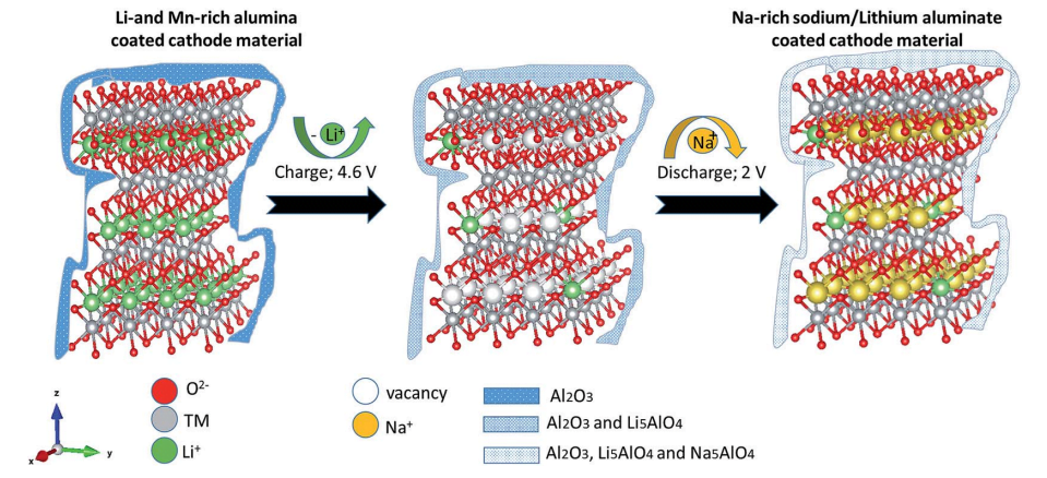
Scheme 1 Ion exchange reactions of the alumina-coated Li- and Mn-rich material.
Structural changes and stabilization of the IENa cathodes upon initial cycling are reflected by the simple consecutive voltammetric measurements and are presented in Fig. 4 (showing four initial cycles). The first cycle exhibits a major very broad anodic peak in the range of 4 to 4.6 V, related to the activation process, and a broad cathodic peak around 3.4 V. The next three cycles are similar but very different from the first cycle. They are characterized by two major anodic processes represented by a broad peak around 3.6 V and a shoulder in the range of 4–4.6 V and a main broad cathodic peak around 3.2 V (a shift of about 0.3 V from the cathodic peak of the first cycle). This voltammetric response reflects the activation and ion exchange processes that occur in the first cycle, following stabilization of a reversible Na insertion cathode.
The electrodes after various processes were measured by HRTEM including selected area electron diffraction (SAED). Fig. 5 shows typical Fourier-transformed electron diffraction patterns of an electrode that underwent activation and sodiation by polarization to 2 V. Patterns of both rhombohedral and monoclinic phases were observed. Characteristic spinel diffraction patterns were observed. Patterns of a spinel phase are usually observed in SAED measurements of Li- and Mn-rich cathode materials after activation (by polarization to 4.6 V).33–36 It is interesting to note that even though the electrode was characterized after discharge to 2 V, a delithiated spinel phase, LixMn2O4 (x / 0), was observed, according to an “a” value lower than 8.044 -A.
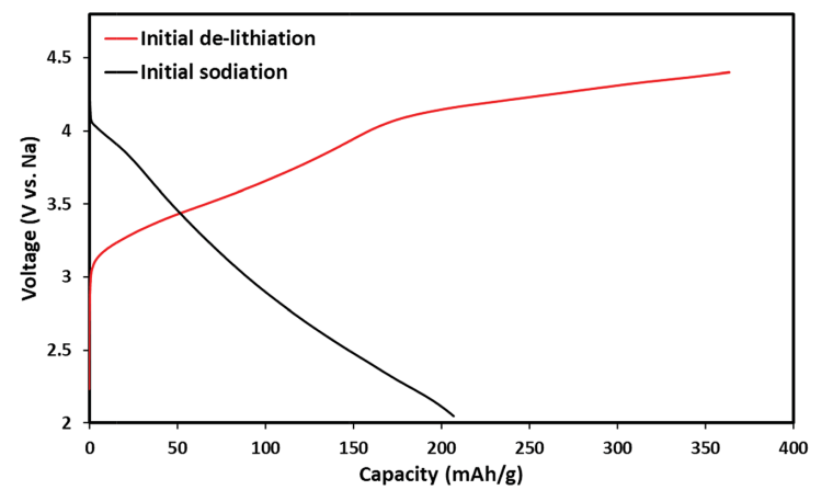
Fig. 2 Electrochemical profiles of initial delithiation (charge) of a Li1.13Mn0.54Ni0.2Co0.13O2 cathode and initial sodiation (discharge) that produces the IENa cathode material in the same cell: 1 M NaPF6 in PC (containing 2% FEC) solution with a Na counter electrode.
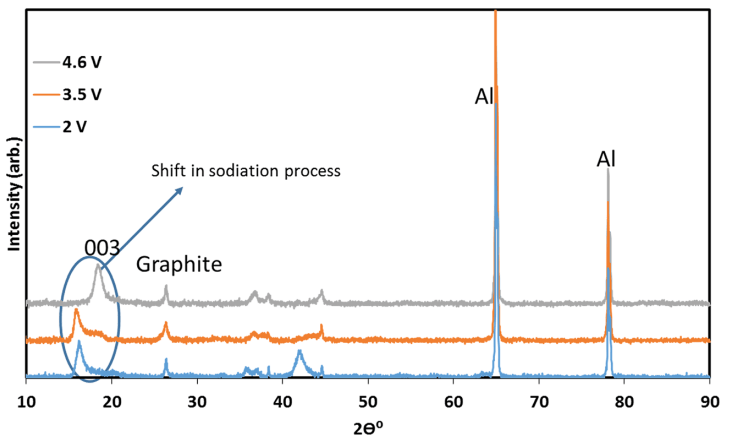
Fig. 3 XRD patterns of IENa cathodes at different stages of sodiation, measured ex situ with the electrodes in which discharge (sodiation) processes were terminated before the XRD measurements at various potentials, corresponding to three stages: after charging to 4.6 V vs. Na, during discharge to 3.5 V, and during discharge to 2.0 V vs. Na (as indicated).
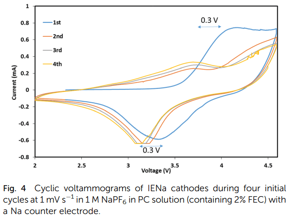
Fig. 4 Cyclic voltammograms of IENa cathodes during four initial cycles at 1 mV s-1 in 1 M NaPF6 in PC solution (containing 2% FEC) with a Na counter electrode.
So far, considering the analysis by electron and X-ray diffraction, we can say that the Li-rich structure with which we started underwent ionization to a Na structure while maintaining its crystal structure.
We attempted to produce cathode materials similar to IENa by a conventional chemical method. The XRD spectrum of the product is shown in Fig. S3. Characterization of the material was carried out by ICP measurements, which also gave a stoichiometry of NaLi0.05Mn0.54Co0.13Ni0.2O2-x (x around 0.1). However, XRD analysis was consistent with the hexagonal structure typical of the NaCo2O4 crystal structure, and the material showed poor electrochemical performance (Fig. S5). Thus, probably due to thermodynamic constraints,37 chemical preparation seems to favor a structure that is neither rhombohedral nor monoclinic, which is devoid of electrochemical activity. The electrochemical ion exchange preparation method therefore appears to be much more successful and is applicable using the process presented above. We conclude that chemical synthesis of potential high capacity Li- and Mn-rich NCM cathode materials is easier and more successful than that of their sodium counterparts of a similar stoichiometry. The excess of sodium ions in such cells ensures in situ formation of a Na insertion cathode and subsequent cell operation dominated by Na ion interactions.
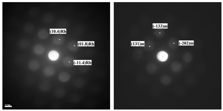
Fig. 5 Electron diffraction patterns (by TEM) of the IENa cathode after the first cycle, followed by discharge to 2 V.
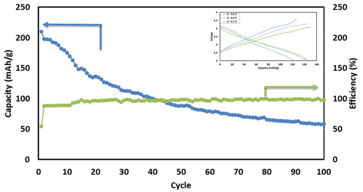
Fig. 6 Typical cycling performance of IENa/Na cells containing 1 M NaPF6 in PC (2% FEC) solution in galvanostatic cycling experiments at 10 mA g-1 (C/10 rate) in the voltage range of 2–4.6 V. The inset shows three typical voltage profiles.
Fig. 6 shows a typical galvanostatic charge–discharge curve (capacity vs. cycle number) for the first 100 cycles of the cells comprising IENa cathodes vs. Na metal anodes. The inset shows several typical voltage profiles. The capacity in the second cycle is about 200 mA h g-1 , but after 30 cycles it significantly decreases to~120 mA h g-1 . However, the cycling efficiency of these cells is nearly 100%, until Na metal anodes reach their expected degradation. We carried out cycling experiments in several voltage ranges vs. Na, with initial charging to 4.6 V to ensure an activation process. Charge/ discharge cycles resulted in a small decrease in capacity; at smaller working voltage ranges (with lower maximum voltage), the cycling efficiency increased. The optimal maximum voltage for prolonged galvanostatic cycling experiments was 4.3 V, with a capacity of 175 mA h g-1 after the second cycle and efficiency of 99.6% with 85% capacity retention after 30 cycles (see Table 1).
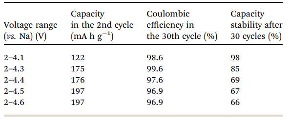
Table 1 Electrochemical behavior of IENa cathodes in half-cells in the second and 30th cycles and after 30 cycles in different potential ranges
Full cells were assembled with cathodes comprising Li1.13Mn0.54Co0.13Ni0.2O2 as the initial active material and anodes comprising pre-sodiated hard carbon (HC) as the active material. The HC electrodes underwent seven cycles of sodiation/de-sodiation before cell assembly. The capacity of the anodes was more than 50% higher related to the cathode capacity. Under these conditions, the initial lithiated cathode material undergoes Li / Na ion exchange to form the IENa cathode material described above. Typical results of galvanostatic cycling of the full cells are presented in Fig. S6. As in the half-cells, the first cycle showed a capacity of 210 mA h g-1 , which decreased after 30 cycles to around 120 mA h g-1 .
The cells that underwent 50 charge/discharge cycles were disassembled, and the cathodes were isolated, thoroughly washed, and dissolved in acidic aqueous solutions, followed by ICP analysis, in order to determine their composition after cycling. The stoichiometry of the resulting cathodes was found to be NaLi0.1Mn0.54Co0.13Ni0.2O2-x (with an experimental error around 3% in the stoichiometric numbers). All cycled cathodes that were analyzed contained residual lithium. We hypothesize that the process of de-lithiation toward IENa is accompanied by transition of some lithium ions to tetrahedral sites. These Li ions do not participate in the ion extraction/insertion activity of the electrodes; they remain steadily in the lattice and may have a positive role in the stabilization of the O phase by preventing movement of neighboring planes.38,39
We conclude that it is possible to obtain high capacity Na insertion materials from direct Li / Na ion-exchange in Na cells with Li- and Mn-rich NCM cathode materials that serve as precursors. However, the cells comprising these cathodes together with Na metal or sodiated hard carbon anodes demonstrate capacity fading during cycling, which depends on the maximal charging potential. These metal oxide cathode materials are known to be reactive with alkyl carbonate-based solution components,40 and therefore we also explored coated materials in which surfaces are protected by an aluminum oxide layer. Such a layer can serve as an interphase that avoids direct contact between the cathode material and solution species, while allowing free transport of Li and Na ions through them.41,42
- Use of Li- and Mn-rich NCM cathode materials coated with Al2O3 as precursors for Na insertion cathode materials
Since activation of these materials by polarization to high voltage forms a highly reactive environment in the cells, Li1.13- Mn0.54Co0.13Ni0.2O2 materials used as precursors for the ion exchange processes described above were coated with alumina by ALD, in an attempt to stabilize them. TEM analysis of the coated powder revealed a 5 nm thick surface alumina layer (Fig. 7). This layer was fairly uniform and was observed on each of the measured particles. Typical electron diffraction patterns of Al2O3 were also observed (Fig. S7). From TEM (Fig. 7) and XRD (Fig. S8) analysis, it appears that no change in the phases of the active mass had occurred. The material retained its monoclinic and rhombohedral composition after the ALD process. ICP and EDS were applied to the pristine material, and the analysis gave an aluminum content of about 6% with respect to the content of manganese atoms in the material (Fig. S9).
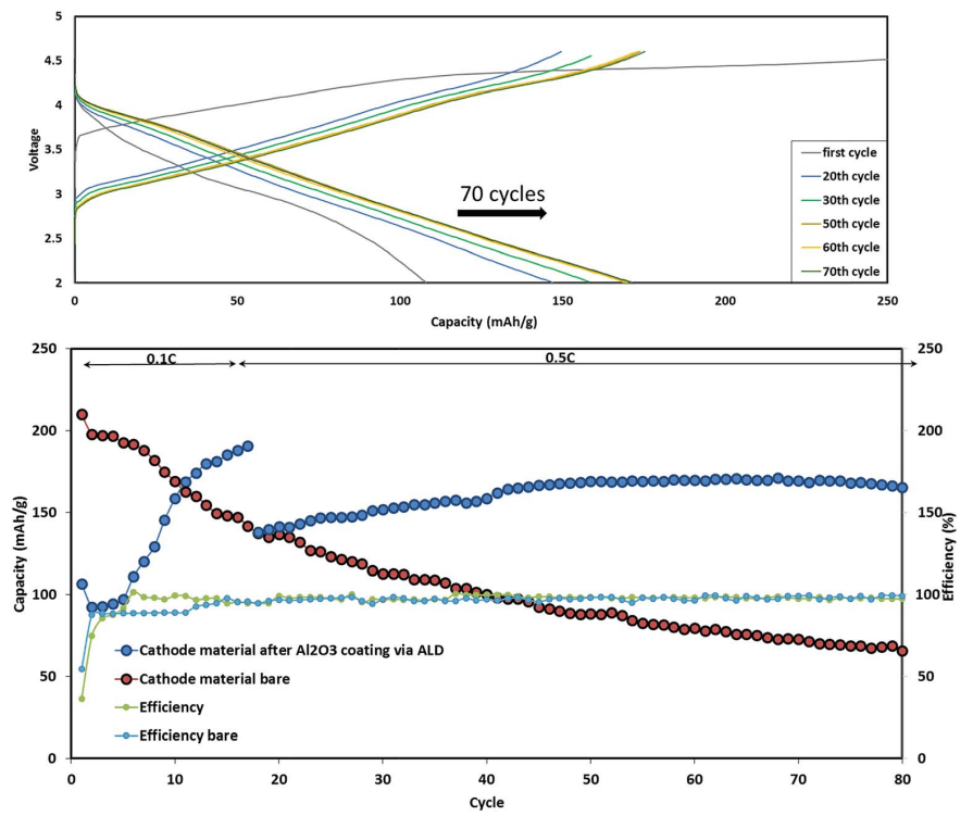
Typical comparative electrochemical characterization results of the Li-a (uncoated) and ALD-coated electrodes are shown in Fig. 8. Both electrodes were cycled in the potential range of 2–4.6 V for 80 cycles. The Al2O3-coated IENa cathode materials show improved capacity and stability: after 80 cycles, the cell exhibits a capacity of 170 mA h g-1 , while the uncoated electrodes show an average capacity less than 100 mA h g-1 . 80 cycles were chosen for stability demonstration, as they allow the cathode performance to be displayed without any interference from the anode side.
Fig. 9 presents the voltage profile as well as the mean voltage during the first 50 cycles of the electrodes comprising the coated and uncoated active mass. The mean voltage of the electrodes comprising the coated IENa material was higher than that of the uncoated electrodes by 0.3 V. Moreover, the mean voltage of the electrodes comprising coated IENa is much more stable in comparison to that of the electrodes containing the uncoated active mass. Hence, the energy density recorded for the cells with the coated electrodes is more than 500 W h kg-1 (of the cathodes) after 50 cycles.
Wise et al. demonstrated that an ultrathin coating of Al2O3 on lithiated transition metal cathodes can significantly improve the situation at the electrode–electrolyte solution interface, reducing the decomposition of the components of electrolyte solutions on high voltage cathode materials.43 Sun et al. suggested that the enhanced electrochemical stability observed for ALD-coated electrodes could be a result of the high band gap energy of the Al2O3 coating layer (Eg ¼ 9.00 eV).44 This could explain that the impressive improvement in performance exhibited by the IENa cathodes is due to coating of the Lia precursor with alumina. Coating of the Li-a particles with an ultrathin Al2O3 layer obviously prevents direct contact between IENa particles and the electrolyte solution and various kinds of possible detrimental side reactions, especially when the electrodes reach high voltages upon charging. Avoiding side reactions should thus increase both capacity and stability upon cycling.
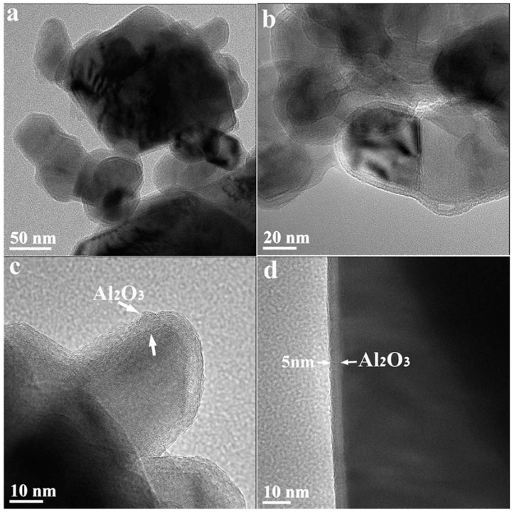
Fig. 7 TEM bright field images of Li-a particles coated with an alumina layer via ALD. Around all measured particles, a thin film (3–10 nm) is visible.

Fig. 8 Upper chart: electrochemical performance of alumina-coated IENa cathodes (blue) and uncoated IENa cathodes (red), presented as capacity and cycling efficiency vs. cycle number in galvanostatic cycling in the potential range of 2–4.6 V. The alumina-coated IENa cathodes were cycled at 0.1C and 0.5C, while the uncoated IENa cathodes were cycled only at 0.1C.

Fig. 9 Electrochemical performance of IENa cathodes: coated (blue) and uncoated (red) materials under the same conditions as in Fig. 8. (a) Voltage profiles in the 10th cycle. (b) Mean voltage.
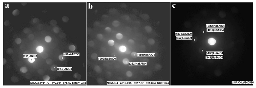
Fig. 10 Electron diffraction (via HRTEM measurements) of the alumina-coated IENa cathode material after 20 charge/discharge cycles in the voltage range of 2–4.6 V vs. Na at a current density of 10 mA h g-1 .
The Al2O3-coated electrode materials were characterized after charge/discharge cycles. Fig. S10 and S11 show XRD patterns and XPS spectra, respectively, of the alumina-coated IENa cathode material after 20 charge/discharge cycles. From the XPS spectra, clear peaks that correspond to the binding energies of Al 2p3/2 (73.3 eV) and of Na 1s (1071.8 eV) are presented. It is evident that the rhombohedral structure is preserved. Support for this preservation was also observed by electron diffraction using TEM for the aforementioned electrode, which showed the presence of both rhombohedral and monoclinic phases. A thin alumina layer cannot be seen using X-ray diffraction; however evidence of its existence and its structural analysis could be obtained by electron diffraction. In addition to the expected alumina layer, orthogonal structures corresponding to formulas Na5AlO4 and Li5AlO4 were observed (Fig. 10). In recent theoretical studies by Han et al., 45 alumina matrices were examined as hosts for lithium and sodium ions. This work was based on experimental studies showing that Li and Na ions can react with an alumina layer to form NaxAlyO or LixAlyO moieties.46,47 This theoretical study showed that the bulk modulus of NaxAlyO sharply decreases as x increases, up to x ¼ 1, and then gradually decreases with a further increase in x. Bulk modulus is a parameter that conveys information about the flexibility of coating materials. A smaller bulk modulus is associated with greater flexibility. In our case, x ¼ 1.25, indicating that the alumina–sodium layer is very flexible. Therefore, it is not broken by stresses exerted during electrode activation. Hence, surface protection by such a layer is steady and effective.
In fact, according to electron diffraction analysis, the presence of an alumina layer together with active metal oxides that are obviously present on these cathode materials induces the following surface reaction:
2.5M2O (M ¼ Li, Na) + 0.5Al2O3 % M5AlO4 (1)
It is well known that upon charging to high potentials, Li and Mn-rich NCM materials undergo a complicated activation process in which oxygen redox reactions are involved.48 There are indications that oxygen moieties such as peroxides are formed, together with some evolution of molecular oxygen.49 Hence, oxides such as Na2O or Li2O can be formed on particle surfaces by disproportionation of peroxide moieties (that also forms O2) and reacts with the alumina layer, resulting in formation of Li5AlO4 surface species. Furthermore, other oxide sites that may not react with Li ions in the first charging process can react in subsequent cycles (which reach potentials at which peroxide species are formed) with sodium ions to form Na5AlO4. The surface films comprising a mixture of M5AlO4 and Al2O3 can serve as a very good SEI, which allows excellent sodium ion transport.
As can be seen in Fig. 8, the first cycles of the cells comprising the coated cathode materials exhibit relatively low capacity which increases until it stabilizes after about 15 cycles. This phenomenon can be explained as follows: at first, there is only an alumina layer at the surface, which behaves as a resistor for ion transport, and therefore the capacity is low. However, in parallel, this layer reacts with lithium ions to form Li5AlO4 and then to form Na5AlO4, which increases the Na ion mobility in the active mass and thereby, the overall capacity of Na ion insertion/de-insertion processes.
To confirm that formation of Na5AlO4 is thermodynamically feasible, we performed density functional theory (DFT) calculations. We used the Quantum ESPRESSO package and the Perdew–Burke–Ernzerhof (PBE) exchange-correlation functional with a plane wave cutoff of 40 Ry. The core electrons of Na, O and Al were represented by pseudopotentials from the GBRV database (http://www.physics.rutgers.edu/gbrv/). The sampling of the Brillouin zone was converged, and k-point meshes of 2x2x2, 3x3x3 and 4x4x4 were used for Na2O, q-Al2O3 and Na5AlO4, respectively.
We used DFT calculations to evaluate the formation energy of Na5AlO4 from binary Na2O and q-Al2O3 oxides. The structures of all three oxides were taken from the COD crystallographic database (http://www.crystallography.net/cod/). The q-Al2O3 form of alumina was used because this structure was detected by XRD. The relative energy of Na5AlO4 formation evaluated based on eqn (1) is -1.4795 eV, showing that its formation is thermodynamically favorable. Thus, in the absence of kinetic barriers, the presence of Na ions, oxygen atoms and Al2O3 should lead to formation of Na5AlO4.
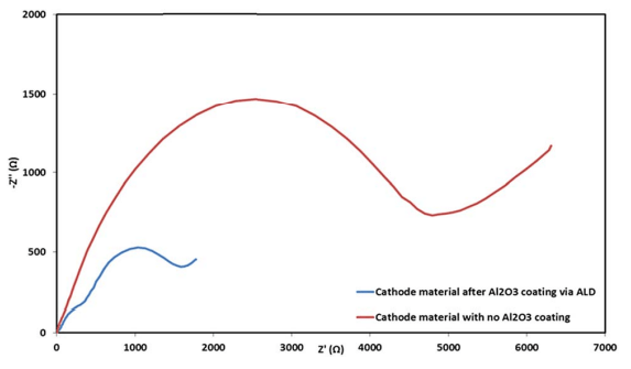
Fig. 11 Electrochemical impedance spectra of coated (blue) and uncoated (red) IENa cathodes in the form of Nyquist plots measured at 3 V vs. Na (upon discharge) after 70 cycles in the range of 2–4.6 V (vs. Na) at 10 mA g-1 in standard coin-type cells containing the 1 M NaPF6 in PC (2% FEC) electrolyte solution.

Table 2 Electrochemical performance of bare and alumina-coated IENa electrodes in cells containing Na metal anodes. The values in the table relate to the 10th cycle
The surprising additional contribution of the alumina layer is the result of eqn (1): it is known that a high reversible capacity exceeding~250 mA h g-1 becomes available only when Li-rich materials are charged to a high potential beyond a voltage plateau near 4.5 V vs. Li, which is related to oxidation of oxygen in Li-rich materials along with lithium ion extraction. Arguably, this oxidation causes some evolution of oxygen and is accompanied by structural reorganization, which leads to a gradual change in the redox mechanism with cycling. The oxygen gas molecules are adsorbed at the surface of the electrode during discharge or extracted from the lattice of the Li-rich materials during charge. Ring-structured carbonate-based solvents, such as ethylene carbonate and propylene carbonate, are known to be vulnerable to chemical attacks by oxygen radicals, which break the ring structure.50 Therefore, various byproducts are formed, such as carbon dioxide, carbon monoxide and water. The oxygen radical can further react with the byproducts, finally forming Li2CO3 as the main product of the side reactions. The Al2O3/Na5AlO4 layer is supposed to mitigate all of these possible side reactions, while enabling a smooth Na ion transfer as a major surface reaction during cycling.
Electrochemical impedance spectroscopy (EIS) analysis was also performed for the electrodes after cycling at 0.5C rate within the potential range of 2–4.6 V during 70 cycles. Representative Nyquist plots of coated and uncoated cathodes measured after 70 cycles at 3 V vs. Na (the Na negative electrode serving as both counter and reference electrodes) are presented in Fig. 11. The difference in the impedance spectra of these electrodes is spectacular. The coated cathodes show pronouncedly lower impedance than the reference, uncoated IENa cathodes. These results support our conclusion so far that significantly lower resistance indicates significant improvement in the active material–solution interface in terms of Na ion transport and fewer side reactions, which form thick and resistive surface films on various kinds of lithiated or sodiated transition metal oxide cathodes.51–54
Table 2 summarizes the electrochemical findings for the coated versus uncoated IENa cathodes as mentioned above. The coating produces a drastic improvement in all cathode parameters: higher capacity, higher mean voltage, much better stability upon cycling, and much lower impedance.
The fact that the cathode materials presented here contain residual lithium in their structure may be advantageous for the electrochemical behavior of these materials as Na ion insertion cathode materials. However, clarifying this issue requires further studies and is beyond the scope of this paper.
Conclusions
In this work, we presented an electrochemical method to directly obtain O3-type materials Na1+xLi0.05Mn0.54Co0.13NiyO2-z (0 < x < 0.1, y ¼ 0.13 or 0.2, z < 0.1) by simple Li / Na ion exchange from Li- and Mn-rich NCM cathode materials as precursors. We found so far that the material could not be produced easily by conventional direct chemical synthesis. This material shows impressive electrochemical performance only in the first cycles. During prolonged cycling, pronounced capacity fading was observed. The stability could be increased upon reducing the working voltage range, at the expense of specific capacity.
Coating Li- and Mn-rich NCM precursors with an Al2O3 surface layer via an ALD process, prior to the ion exchange process, produced sodium intercalation cathode materials with pronouncedly improved performance, as summarized in Table 2. We found that the alumina surface layer is partially converted to Li5AlO4 and Na5AlO4, probably by reaction with Li2O and Na2O. The latter may be formed by disproportionation of metal peroxide species, which are formed upon activation of Li-rich NCM cathode material precursors by polarization to high potentials. This process also releases molecular oxygen. The surface layer comprising alumina and Na5AlO4 forms an excellent passivating SEI that transports Na ions very well and avoids detrimental side reactions between the cathode material and electrolyte solution species, as expressed by the stability and low impedance of the cathodes that comprise the coated active mass.